|
Online Sun Information ArcHive
|

|
501-1638
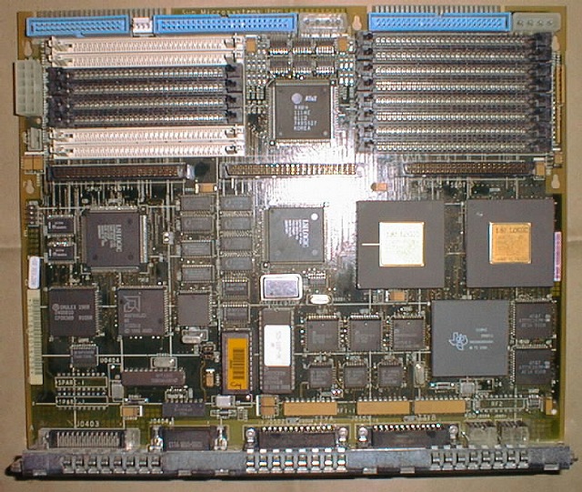
4/75 (SPARCstation 2) motherboard 16M FCC-A
50MHz CY7C601 @ 40MHz, TI TMS390C601A (602A ?), Sun-4c MMU with 16 hardware
contexts. 20MHz SBus.
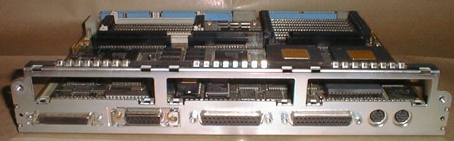
From left to right, the rear edge of the board has: a 50-pin SCSI-2 connector;
an Ethernet connector; two serial port connectors (ports A and B from left to
right); an 8-pin-DIN keyboard/mouse connector; and an audio connector.
Connector pinouts and form factors are not known.
Memory consists of up to sixteen 4M x 9 80ns 30-pin SIMMs. The SIMM slots are
arranged in four groups of four. Electrically, there are four "banks," each
of which is composed of one slot from each group:
Back of machine (nearest SBus connectors)
-------U0311------ 0 0 -------U0322--------
bits -------U0312------ 2 2 -------U0321-------- bits
24-31 -------U0313------ 1 1 -------U0320-------- 0-7
-------U0319------ 3 3 -------U0316--------
-------U0309------ 0 0 -------U0307--------
bits -------U0310------ 2 2 -------U0308-------- bits
16-23 -------U0314------ 1 1 -------U0315-------- 8-15
-------U0318------ 3 3 -------U0317--------
Front of machine (nearest disk connectors)
Banks must be filled in order (0 through 3). THERE IS SOME DISPUTE OVER WHICH
SLOTS BELONG TO WHICH BANKS. The Sun Field Engineer Handbook for 12/15/93
says that the banks are in order (i.e. 0, 1, 2, 3 from back to front), but
other sources agree that they are in the interleaved order shown above.
There are a variety of jumpers. All locations are given with component side
up and connector side toward you.
J0705 (block along the near right edge)
Described only as "SAX" and apparently all pins jumped by default.
GND1 (single jumper in middle right edge)
Unknown.
GND2 (single jumper in nearish leftish)
Unknown.
GND3 (single jumper in near rightish)
Unknown.
(pair of horizontal three-pin jumpers in near left) Jump left two pins for
RS232 serial ports, right two pins for RS423 serial ports.
Additional features of interest: the boot PROM is in the near middle at
location U0501. The NVRAM/TOD/ID chip is to the left of the boot PROM at
location U0512. At the far left edge and the far edge, from left to right,
are the floppy power, power, floppy, LED/speaker, and two pairs of internal
SCSI and disk power connectors.
Note that the SPARCstation 2 was first supported in SunOS 4.1.1.
Note that the 501-1667 Load Board should be installed in systems without disk
drives or SBus cards.
Power requirements with 16M of 4M SIMMs are +5V @ 3.6A.

[ home ]
[ hardware ]
[ software ]
[ more... ]
[ search ]
[ layout ]
   Last modified: 2001.11.24.18.41.00 CST
     Server time: 2008.12.06.04.25.40 GMT